F33 Rear Wing
Aerodynamic Design
A tri-element, two-profile-primary rear wing for RIT's F33 electric Formula SAE car.
I was an aerodynamics design engineer for RIT's FSAE team for F33 and part of my job was designing a rear wing for our electric race car. The hardest part of this design was navigating the tradeoffs between downforce, drag, mechanical constraints, and manufacturability.
F33's rear wing builds directly on lessons from the outgoing F32 car. I kept the tri-element architecture that worked well last year and focused every new decision on three goals, extract more downforce at low-speed cornering, cut parasitic drag at top speed, and help design a rigid, serviceable package.


Key Results
All figures taken from the full-car Fluent 23R2 simulation at the design-point cornering velocity (24.8 mph), with the k-ω SST turbulence model, a rotating-wheel reference frame, and a moving ground plane.
24.62 lbf
DOWNFORCE
at 24.8 mph design point
10.36 lbf
DRAG
rear wing isolated
2.376
L / D
10.51 lb
ASSEMBLY MASS
F33's rear wing makes 1.396 lbf less downforce than F32's wing, the F33 package runs a top/bridge wing and a revised ground-effect undertray, and interaction with the undertray (UT) alone accounts for a 2.25 lbf reduction on the rear wing. The design decisions below (moustache primary, endplate notch, swan-neck mount, lateral-rigidity bar) were made to recover that downforce and increase efficiency on top of it.
Speed-Scaled Rear Wing Contribution · Full-Car Extraction
The headline numbers above are extracted from the 11.1 m/s cornering design point. For reference, the full-car sim scales the rear wing's contribution roughly with V² across the operating envelope:

The overspeed 45 m/s case is the structural envelope: a worst-credible straight-line run with a 20+ mph headwind, used to size the swan-neck mounts, lateral-rigidity bar, and bonded inserts.
F33 Car-Level Targets vs. F32
Total-Car Downforce vs F32
+40.3%
F32: 256.56 N · F33: 268.95 N at 11.1 m/s. Falls short of the 359.95 N target (-25.3%) but is a meaningful step over the outgoing car.
Total-Car CLA vs F32
+31.9%
F32: -3.412 · F33: -3.564. The car generates meaningfully more load per unit dynamic pressure.
Aero Balance vs F32
+14%
F32: 43.0% front · F33: 49.3% front. Much closer to the 49.0% target, the rear wing is no longer forced to over-work to compensate for a front-biased car.
��Moustache primary as an isolated element
These deltas are for the primary element in isolation, comparing the spanwise-split "moustache" primary against a single-airfoil, uniform-span primary at the same design condition. They quantify the value of the two-profile spanwise layout as a design decision.
Downforce Δ vs. single-profile
+20.76%
7.07 lbf to 8.55 lbf. The outer BE 153-105 sections run at 7.25° in clean freestream; the middle GOE 227 section stays efficient at 5° in the driver's helmet wake.
Drag Δ vs. single-profile
-22.10%
0.867 lbf to 0.675 lbf. Matching airfoil and AOA to the local flow quality drops parasitic drag in the middle span where a higher camber profile would have separated.
L/D Δ vs. single-profile
+54.96%
8.165 to 12.653. The compounding effect of more lift and less drag. L/D is the metric that matters most for an FSAE car that spends most of its life in corners.
Outer-section AOA sweep
I ran the BE 153-105 outer-section alone through a seven point AOA sweep to land the primary's outer angle. The 11.75° point failed to converge.

Full-car sim, 11.1 m/s, half-symmetry. CLA and CDA are per-half-car. L/D climbs with AOA until ~7° then falls. 7.25° was chosen as the design AOA because the CLA gain over 5.25° (+3.1%) matters more to a cornering-limited car than the L/D gain on an efficiency-unconstrained straight, and it still holds a 3.5° cushion to the 11.75° stall boundary where the sim fails to converge.
Wing Elements
How the profiles were selected
Before the full-car design loop, I ran isolated-airfoil CFD on ten candidate profiles, GOE 227, GOE 447, GOE 448, GOE 464, FX 74-CL5-140 MOD, E423, AH 79-100 C, and Benzing profiles BE 122-125, BE 122-155, BE 153-055, BE 153-105, shortlisted against three goals: high CL, high L/D efficiency, and the ability to run more aggressively on the outer span than on the driver-wake-fed middle span.
The GOE 227 dominated the L/D comparison by a meaningful margin over every other candidate. Even when other profiles out-lifted it, the efficiency gap was wide enough to make GOE 227 the default middle-span pick, especially given the uncertainty we were carrying around a potential move to in-hub motors, which would have shifted the car's drag budget. The BE 153-105 was the cleanest companion for the outer span, higher CL than the 227, still efficient, and stall behavior that leaves margin at the target Reynolds number.
Isolated-airfoil runs are only valid for shortlisting. Once the profiles were picked, every downstream decision, AOA, slot geometry, spanwise split, endplate, was made in full-car CFD that ingests the driver-helmet wake and sidepod upwash. The isolated runs would have over-predicted downforce on the installed wing.
Speed Envelope
20-65 mph
8.94 – 22.35 m/s
Chord Design Window
14-17 in
0.356 – 0.432 m
Reynolds Number
2.78 – 8.35e5
avg Re ≈ 4.17e5
Isolated-airfoil CFD · candidate shortlisting


Inner Pressure
Outer Pressure
Outer Velocity
Inner Velocity


Primary Element bi-profile
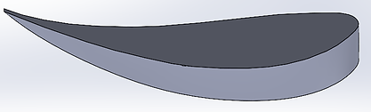
GOE 227 + BE 153-105 · 37" span
Inner Profile GOE 227
Inner AOA5.00°
Outer Profile BE 153-105
Outer AOA7.25°
Span 37 in
Total Chord 15 in
The middle section runs the efficiency-biased GOE 227 at a modest 5° AOA because it sits directly behind the driver's helmet, where the flow is dirty and a more aggressive airfoil would separate. The outer sections run the higher-lift BE 153-105 at 7.25° where the air is clean.
Secondary Element
BE 122-155 · 9" chord w/ 1.125" cut
Airfoil BE 122-155
Chord 9 in
Chord Cut 1.125 in
Slot Gap 0.633 in (2.57%c)
Overlap 0.766 in (3.11%c)
AOA 30°
Carried over from F32 with tightened slot geometry. The gap and overlap are sized to accelerate flow through the slot, re-energize the primary boundary layer, and keep the secondary attached all the way to the trailing edge at its 30° setting.

Tertiary Element w/ gurney

GOE 448 · 4" chord · 0.4" Gurney
Airfoil GOE 448
Chord 4 in
Slot Gap 0.299 in (1.22%c)
Overlap 0.533 in (2.17%c)
AOA 60°
Gurney 0.4 in ⟂ chord
The tertiary runs at an aggressive 60° AOA behind a short slot. A 0.4" tall Gurney flap, mounted perpendicular to the chord rather than the trailing edge, shifts the Kutta condition off the trailing edge and onto the tip of the flap which extends both the effective chord and the effective camber of the airfoil. The counter-rotating vortex pair shed behind the Gurney acts as a virtual streamline extension, lifting circulation into the wake without a proportional drag cost.
At ISA sea level with a 15" (0.381 m) chord, the primary operates between Re = 290,000 at the cornering speed of 11.1 m/s and Re = 886,000 at the 33.975 m/s design top speed. That puts the wing in the low Re regime where laminar to turbulent transition is sensitive to small changes in AOA, surface quality, and incoming flow conditions.Behind the driver's helmet the air arrives at the middle section with lower velocity and higher turbulence, lower local Re and a messier boundary layer. The GOE 227 at 5° is chosen because it stays attached and efficient in that degraded flow. The outer sections see clean freestream at full Re, so they can handle the more aggressive BE 153-105 at 7.25° without risking early separation.
Top Wing Interaction & Primary Chord Iteration
Sizing the rear wing around the bridge.
F33 has a top/bridge wing mounted above the main rear wing, it's job is to recover some of the downforce lost to the revised undertray, but its wake interferes with the primary's leading edge, which meant the rear wing had to be re-sized in the presence of the top wing.
I ran CFD sweeps with the top wing installed at 8°, 15°, and 30° AOA (with and without its Gurney flap), and used those runs to iterate primary chord length from 13", 14", 15" as well as a variety of slotgaps/overlaps. Shorter primaries made the rear-wing system easier to pack under the bridge but sacrificed enough lift that the top wing could not make up the delta. The 15" chord was the shortest primary that kept the full tri-element system on its L/D ridge at the cornering design point.


Secondary × tertiary AOA, full response surface.
The secondary and tertiary slot elements don't optimize independently, moving one moves the other's effective freestream, which moves its best AOA. To find the real joint optimum I ran a full two-axis AOA sweep over the secondary (27° – 33°) and the tertiary (55° – 75°), and reconstructed the response surfaces for integrated lift and L/D across the entire envelope.

Fig 01 · Lift Response Surface
Lift vs. Secondary & Tertiary AOA
Lift climbs steadily with secondary AOA and peaks near the top of the tertiary range before the tertiary begins to stall.

Fig 02 · L/D Response Surface
L/D vs. Secondary & Tertiary AOA
The selected design point (Secondary 30°, Tertiary 60°) sits on the L/D ridge, biasing the wing toward efficiency at the cornering speeds where it actually works.
A single-axis sweep assumes the elements behave independently when they really don't. Each element's circulation induces upwash on the element behind it, which changes the effective AOA the downstream element sees. So when I change the secondary's geometric AOA, I'm also changing the tertiary's effective AOA, even though the tertiary hasn't physically moved. The coupling runs both ways: the tertiary's circulation upwashes back into the secondary too.
The design point was chose to balance lift and L/D, and a safe distance back from the separation boundary, leaving margin for gusts, crosswinds, and pitch changes during cornering. The graphs have the AOA axis reverse of each other to make it a bit easier to see the surface shape, though it does make it a bit harder to intuitively read.
Selected Design Point
Lift 135.85 N · Drag 42.08 N · L/D 3.228. Sits on the cooperative plateau where both slot elements carry load without the tertiary dipping into separation.
Sec 30° / Tert 60°
Peak Lift Point
Lift 159.21 N · Drag 56.65 N · L/D 2.81. Highest converged downforce in the envelope — rejected because the tertiary stall boundary is immediately adjacent and L/D drops 13% vs. the design point.
Sec 32° / Tert 69°
Alternate Ridge Point
+9.9% L/D, −1.4% lift vs. the design point (L/D 3.547 · Lift 133.91 N · Drag 37.76 N). Rejected because it neighbors a non-converged cell (Sec 31° / Tert 54°) — too close to the separation boundary to trust as a race setting.
Sec 31° / Tert 57°
High-Lift Secondary
Lift 153.07 N · Drag 47.50 N · L/D 3.22. A viable aggressive alternate if the car spec ever demands more lift at the same L/D. Flagged as the high-downforce fallback for an endurance-only setup.
Sec 31° / Tert 67°
Peak L/D Point
L/D 3.566 · Lift 123.32 N · Drag 34.58 N. Corner-of-the-sweep efficiency maximum. Not selected because the lift is 9.2% below the design point — efficiency only matters if the wing still does its job.
Sec 29° / Tert 51°
Envelope Notes
design points converged cleanly after corrections. The Sec 32° row and most Sec 33° points at extreme tertiary AOAs blew up numerically.
27 of 35
Primary Outer-Section AOA Study
The outer BE 153-105 sections were swept independently to land the 7.25° design AOA, it's the angle that maximizes the lift contribution from those outer sections without stalling them.


Slot Gap & Overlap · Design of Experiments
Slot gap and slot overlap are the two geometric parameters that most directly govern how effectively flow accelerates between the primary and secondary elements. I ran an 18-point Latin-hypercube-style DOE on the secondary element alone (primary + secondary, no tertiary) at 11.1 m/s, sweeping overlap from 0.15" to 4.56" and gap from 0.15" to 4.83", then a second refinement pass of 13 more points clustered around the early winners.
The DOE identified a +43% L/D opportunity at wide slot geometry (DP 16), and it confirmed that slot × tertiary coupling is strong enough that the tertiary element's best AOA shifts when the slot changes. Eight of 31 points didn't converge at the extremes of the sweep, those cells define the mesh-trust boundary for future work, but the converged cluster cleanly brackets the real optimum.

Showing the seven converged design points from the 31-point sweep. DP 16 is the L/D winner at +43.4% over the tight-slot baseline. The omitted points all sit at the extremes of the sweep, they define where the slot mesh stops being trustworthy, which is itself useful information for bounding the next DOE.
DP 16 proved the +43% L/D opportunity is real. What it also proved is that the slot doesn't optimize independently, opening the gap between primary and secondary changes the velocity profile the tertiary ingests, which shifts the tertiary's best AOA by several degrees. The 2D AOA sweep in the previous section was run against the F32 slot, re-running it against DP 16's wider slot would have moved the design point, which would have moved the structural and chord-length decisions downstream of it.
Recovering the +43% requires a joint slot × tertiary-AOA DOE, a 4-parameter optimization against a mesh that we already know doesn't hold up at the sweep extremes. F33 runs the geometry (gap 0.633" / overlap 0.766") where the full tri-element cascade had validated tuning and the mesh had the most convergence confidence.
Full-car CFD with a moving ground plane.
The rear wing was never simulated in isolation for the final design loop. Everything shown below was pulled from full-car Ansys Fluent 22R2 runs with a rotating-wheel reference frame, a moving ground plane matched to freestream velocity, and the k-ω SST turbulence model.
Load cases
I ran the wing at three operating points, the average cornering speed of 11.1 m/s, where the car spends most of it's time, the design-point top speed of 33.975 m/s, and a 45 m/s overspeed case representing a worst-credible straight-line run with a 20+ mph headwind.


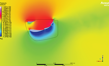
Center view of pressure from full car
Center view of pressure from full car
(see separation from roll hoop on bridge)


Edge view of pressure from full car
Edge view of pressure from full car


Wing Endplate
Trailing-edge notch
The notch on the trailing edge deliberately interferes the wing-tip vortex with the high-pressure-side spillover vortex, producing partial vortex cancellation. It's a subtractive geometry choice — removing material where it costs induced drag.
Swept front and bottom edges
Sharp corners shed discrete vortices at every AOA. Sweeping the front edge and the lower edge of the endplate smooths the pressure mix between high- and low-pressure sides, which reduces the strength of the structured vortices that form at those edges.
Size
Sized large enough to hold the low-pressure field on the suction side, but not so large that it blocks service access to the drivetrain and accumulator — both of which live directly under the wing and have to come out fast in the paddock.

Structure & Mounting
I helped with the structural design side of the wing, working with others in the group on the mounting architecture, the primary element's internal construction, and the stiffness strategy that keeps the wing from twisting under cornering load. Dedicated FEA was handled by others in the group, the focus here is on the design decisions and the aerodynamic reasoning behind them.
Swan-neck mounts
The swan necks hang the wing from the low-pressure (suction) side of the primary. That one decision eliminates the aerodynamic penalty of a conventional strut crossing the low-pressure underside.
Compared to the F30's legacy mounting system, the swan necks reduce disturbance to the suction-side flow through a smaller frontal area, increase rigidity through a stiffer load path to the chassis, and make wing servicing dramatically easier, the wing can be pulled without disconnecting the structure of the rear subframe.
They are angled inboard to add a lateral stiffness component to the mount, which is what resists the side-to-side wing loads that come from yawed flow in cornering.


Lateral rigidity bar
A carbon bar bridges the two swan necks behind the wing, triangulating the mount so the wing can't yaw about the chassis. The bar replaces the F32 endplate-to-chassis struts, which created their own drag and complicated servicing.
The aerodynamic penalty is negligible, but the side-to-side stiffness it adds to the mount meaningfully cleans up the wing's pitch behavior under cornering load.
Rib-and-spar primary
F32 built its primary on steel tubes bonded into the skins. That worked for a straight-camber single-profile primary, but the F33 two-profile primary has a compound camber line that can't be matched by a circular tube.
I worked with others in the group on a rib-and-spar composite primary, chordwise ribs that match the GOE 227 + BE 153-105 compound profile, a forward and aft spar that carry the bending load out to the swan-neck pickups, and skin-to-rib bonding that preserves the airfoil surface to match the CAD loft.
The spar positions were chosen to align with the swan-neck pickup fittings, so the load path from the suction peak into the mount is essentially straight.


Validation
Ford Wind Tunnel 8 correlation January 2025.
We took the outgoing F32 to Ford Wind Tunnel 8 in January 2025 and swept six speeds from 11.4 m/s to 32.1 m/s at 1.5" ride height, 0° pitch, 0° roll. Then we matched the conditions in the full-car CFD and compared.
Full-car sim vs. tunnel
~35%
Average over-prediction of total downforce across the speed sweep.
Undertray-removed sim vs. tunnel
3 – 10%
When we subtract the sim's undertray contribution and compare against the measured non-undertray signal, agreement is within single-digit percent across every speed. The rear wing, front wing, and sidepods correlate well.
The 24.62 lbf / 10.36 lbf headline at the top of the page is pulled from the same full-car CFD method that, on F32, matched the tunnel to within single digits on everything except the floor. The sim's issue is localized to the undertray, it doesn't propagate into the rear-wing numbers. This is due primarily to the lack of a rolling floor at Wind Tunnel 8.


